Dummy HDMI adapters

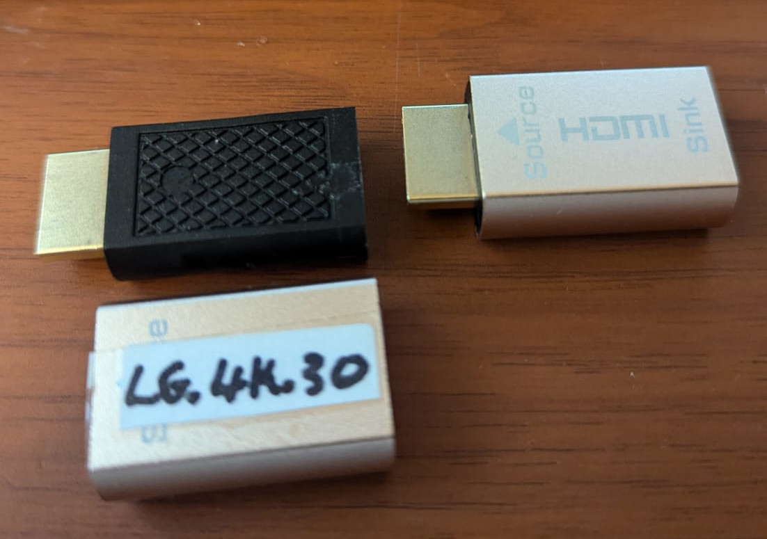
A nice adapter that has both input and output is this which i got from AliExpress (Photos at the bottom)

This 4K dummy adapter seems to support all resolutions up to 60Hz refresh rate, with the exception of 4K which works at a maximum of 30Hz (Probably due to signal attenuation)

There are many uses for this dummy adapter, one of them is “Sunshine and moonlight remote desktop”, another is using your GPU for processing while you are away (Nvidia won’t allow it if you don’t have a monitor connected and switched on), and most importantly TO ME, My video switch since I use multiple machines on the same monitor.

What this adapter is in reality is an eeprom chip that has the EDID data of a monitor with a very high refresh rate (120 hz), namely a fictitious monitor named AOC 28E850, If you want to make sure that this works with your monitor, it needs to be flashed with your monitor’s EDID.

If your monitor supports 4K at 60hz, you need to keep everything in that copy, and remove the 4K.60Hz from the list

If you want the modified file that originated from my LG 27UL550 and was modified to remove the 60Hz from the list of supported configurations, meaning I removed the 60 FPS from the 4K DTD, then here it is, just download it and flash it (Flashing instructions below) I also changed the monitor’s name just in case some systems might cache it’s details…

The steps

1- Find out the port on your graphics card that your monitor is connected to

2- Copy the EDID data from your monitor

3- Edit the data to remove the 4K/60 fps
4- Burn the data onto the adapter

To do that, there are many tools, one thing to note is that edid-rw did not work using my laptop which has a 9400mx, but worked just fine using an old PC i have with a “GT218 [GeForce 210]”, the error on the laptop reads

sudo ./edid-rw 5
Traceback (most recent call last):
File “./edid-rw”, line 131, in
main()
File “./edid-rw”, line 119, in main
edid = [dev.read(i) for i in range(EDID_HDR)]
File “./edid-rw”, line 46, in read
return self.smb.read_byte_data(EDID_ADDR, n)
IOError: [Errno 110] Connection timed out

edid-rw tool: https://github.com/bulletmark/edid-rw
wxedid tool: install from debian repo

I personally used the tools above to read/write/edit, but if you have access to a windows machine, AW-EDID should be the best tool for editing….
Analog Way EDID editor: https://www.analogway.com/apac/products/software-tools/aw-edid-editor/

So, let’s get down to that voodoo business !

1- There seems to be a very cool python script (tool) called edid-rw, let us install it’s prerequisites

sudo apt-get install python3-smbus edid-decode git

Now, you have python, let us download the tool, you can do that with the download button on github, I would rather just

git clone https://github.com/bulletmark/edid-rw
cd edid-rw

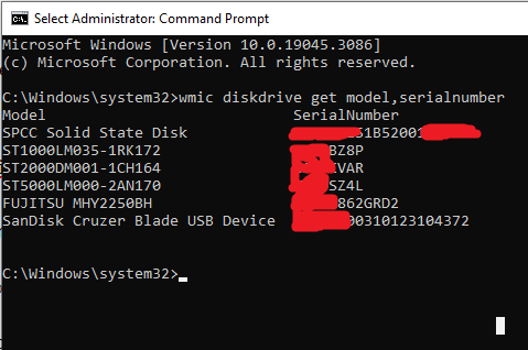
To begin with, you may need to run the following command to see what monitors are connected where, In my case, the monitor I want to copy (LG 4K 60FPS) is #5

xrandr --query

If this does not help, try the numbers and read the output to see which entry corresponds to the screen you want
sudo ./edid-rw 5 | edid-decode

Now that we have it, we can edit it with one of the software mentioned above, and dump it back on the dongle (The port number does not change, so put your number there and dump the data onto it)

udo ./edid-rw -w 5 < ~/edited_lgedid.bin

Text from the original page of the item

Support hot plug, plug and play
Support virtual display, when the display is powered off or the display cable is hot-plugged, It can achieve no video signal loss, no screen change, no windows running, no order disorder;
Support up to 10.8Gbps video bandwidth; It has power-off memory function, power-off/restart display sequence is not chaotic, and the set mode is not lost.
Supports for AMD multi-screen image card splicing extended split-screen mode, eyefinity wide-area multi-screen splicing mode (pulling the monitor cable when it is powered on has no effect on the display of the screen TV wall, and pulling the line will only cause the screen of the dropped line to be black, and other screens will not move)
Support Nvidia image card multi-screen output, the screen sequence is not chaotic after restart

Connect typ:HDMI
Application scope: Display with HDMI interface
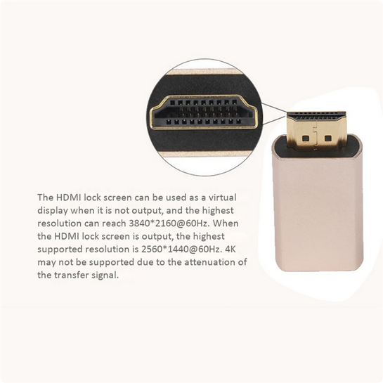
Product name :HDMI lock screen treasure
Max Resolution : 2560 x 1440@60HZ / 3840 x 2160@60HZ
colour:Golden
Material:Aluminum alloy

Package Contents:
6 x HDMI2.0 Virtual Adapter

The aluminum sleeve appears to be fully cosmetic, At least this is my impression as the plastic inside seems very hard, so it is unlikely that the aluminum is providing any support, and obviously is not functioning as any form of heat sink

Sunshine and moonlight

VNC and RDP are great and all, and for so many purposes, they are the goto solution for remoting into a machine.

Now, another solution which is great (And much better if you have the bandwidth) is to broadcast your screen video and do all the work on the server rather than the client

The solution used to be nvidia’s game stream, which was abandoned by nvidia, the new solution based on nvidia would be the sunshine (Server) and moonlight client

The sunshine+moonlight duo work on almost every platform I need, Windows, Mac, Android, iOS, Even LG TVs running web OS… in short, it is a more universal solution. You can even create a virtual non existent monitor under linux and stream that to a different device !

So, let us start with the server (Sunshine)

Installing sunshine on debian is very easy as a .deb installation file is provided, sunshine is not yet in the debian repositories, but if i understand the license correctly, it can be some time in the future

Now, go to the sunshine website, and download the deb file., in my case, I visit this webpage, and download the sunshine-debian-bookworm-amd64.deb file

Now, from the command prompt, su (to run as root), then cd to the directory where your deb file resides, then “sudo apt install ./sunshine-debian-bookworm-amd64.deb”, We should now have the server running and waiting to be opened in the web browser, Now, on the command line , type “sunshine”

Point a web browser to https://localhost:47990/, ignore the problem with self signed certificates, and set your username and password

Now, your debian computer is running a sunshine server, go to any other machine where you want to install the client (moonlight) from here , and connect to your server by its IP address.

You are done !

GPU PCIe passthrough on KVM

Before you start

This may look like a long post at first, but in reality, it is but a few commands, the rest is output and small simple explanations, so don’t be discouraged by the length, it is really neither complicated nor lengthy.

Yet, you do need to check the hardware requirements before you get your hands dirty, you will find them in the “Minimum hardware requirements” section of this post

Continue reading “GPU PCIe passthrough on KVM”

Hard drive power draw at startup

The maximum power draw a PC with many hard drives happens at boot time, in my case, the PC is a n intel atom D525MW, which hardly draws any power

What this means is that I need an oversized power supply that only does its thing at startup, then becomes an inefficient power supply right after, why this is particularly important is because this computer runs on a UPS, and the number of minutes it can stay up is a very important number.

The solution is to enable PUIS (Power up in standby), what this does is allow the disks not to spin as soon as they get power, but instead, spin up upon reception of a command from the controller. so in effect, the disks are spun up sequentially (In turn).

Continue reading “Hard drive power draw at startup”

Mounting QCOW2 (KVM/QEMU) directly

First, the tools you need

apt-get install qemu-utils

Now, enable NBD

modprobe nbd max_part=8

Once that is enabled, connect the file as a block device

qemu-nbd --connect=/dev/nbd0 /hds/usb/virts/Windows/main.qcow2

Now, the block device should appear like any other, alongside the partitions inside !

fdisk -l

On my machine, this resulted in

Disk /dev/nbd0: 95 GiB, 102005473280 bytes, 199229440 sectors
Units: sectors of 1 * 512 = 512 bytes
Sector size (logical/physical): 512 bytes / 512 bytes
I/O size (minimum/optimal): 512 bytes / 512 bytes
Disklabel type: dos
Disk identifier: 0xc5324c42

Device      Boot     Start       End   Sectors  Size Id Type
/dev/nbd0p1 *         2048    104447    102400   50M  7 HPFS/NTFS/exFAT
/dev/nbd0p2         104448 198138958 198034511 94.4G  7 HPFS/NTFS/exFAT
/dev/nbd0p3      198139904 199225343   1085440  530M 27 Hidden NTFS WinRE

This disk was around 40GB, but fdisk will see the number corresponding to the largest allowed size, 100GB in this case ! let us mount the drive

mount /dev/nbd0p2 /hds/loop

Now, in this case in particular, like any other block device that held the windows operating system, more often than not, you will get the message saying

The disk contains an unclean file system (0, 0).
Metadata kept in Windows cache, refused to mount.
Falling back to read-only mount because the NTFS partition is in an
unsafe state. Please resume and shutdown Windows fully (no hibernation
or fast restarting.)
Could not mount read-write, trying read-only

The solution to that is simple, follow the following two steps to remedy the issue and then force mount the file by using remove_hiberfile

ntfsfix /dev/nbd0p2
mount -t ntfs-3g -o remove_hiberfile /dev/nbd0p2 /hds/loop

The result of NTFSFIX was

Mounting volume... The disk contains an unclean file system (0, 0).
Metadata kept in Windows cache, refused to mount.
FAILED
Attempting to correct errors...
Processing $MFT and $MFTMirr...
Reading $MFT... OK
Reading $MFTMirr... OK
Comparing $MFTMirr to $MFT... OK
Processing of $MFT and $MFTMirr completed successfully.
Setting required flags on partition... OK
Going to empty the journal ($LogFile)... OK
Checking the alternate boot sector... OK
NTFS volume version is 3.1.
NTFS partition /dev/nbd0p2 was processed successfully.

And the following mount command worked as you would expect, silently

Now, if you want to disconnect the NBD image, you need to unmount (Like you normally would) THEN

#Disconnect the image from the NBD device
qemu-nbd --disconnect /dev/nbd0;
#Unload the NBD module
rmmod nbd;

Linux badblocks cheat sheet

1- Large disks need to have their block size specified, without it, disks like my 6TB and my 8Tb hard drives will not work, badblocks will report the following error.

badblocks: Value too large for defined data type invalid end block (5860522584): must be 32-bit value

So the solution is to add the block size, like the following for example (This one is destructive)

badblocks -b 4096 -wsv /dev/sdb

It is a good idea to LOG THE BAD SECTORS (this is the command i usually use for a destructive test)

badblocks -b 4096 -o /root/badblockslog.txt -wsv /dev/sdb

In the command above, the W means do a destructive red-write test, the S is for show progress, and the V is for show the errors you encounter, the -o flowed by a file name is where to keep the log file

USB over IP (network)

Hyper-v does not provide USB passthrough, some people use USB redirection from remote desktop RDP… A similar technology might be USB over network, but this does not always work, as many USB devices have very little tolerance for lag ! and this will introduce some lag !

My objective is to connect a MINI-VCI connected on a raspberry PI to a computer running other software to analyze the data, whether this works or not is yet to be seen.

There seems to be a few solutions online, some using generic hardware, and some using specialty hardware

The most diverse of those solutions that can work on everything from a raspberry pi to a windows computer and android phone is (https://www.virtualhere.com/), but I have not yet verified whether this software is USB/IP compatible or not

USB/IP has been built into the linux kernel for some time now, and a couple of solutions for both server and client are available on github, So here I will be investigating what I can do to bridge the Linux Raspberry PI to my windows PC,

USBIP is a protocol where the server is the machine connected to the USB device via wire, and the client is the machine that needs to use the USB device but is not connected to it via USB.

In linux, usbipd is the name of the server, and usbip being the client, In debian, both server and client are included in the usbip package, hence, on the raspberry PI and on the Linux server, we need to run the command

apt-get install usbip

The modules of USB/IP (usbip-core, usb-host, and vhci-hcd) are already included,

We will get to the Windows client after the Linux to Linux section

The two options

In the cases we are exploring here, the server is a Raspberry Pi (3), the client is a Windows machine, but there are a couple of things to try first, the Windows clients are KVM virtual machines, we will try

1- The client is the Linux Host machine hosting the windows virtual machines, and the USB port is passed to the virtual machine

OR

2- The Windows client has the USBIP driver directly connecting to the Raspberry PI server

The Steps

Installing the USB/IP server on the raspberry pi “apt-get install usbip”

Why does my SSD slow down on copying large files

So you have a budget SSD, something like the Kingston A400, and half way through a multi gigabyte file it slows down !

Coming to think about it, this SSD does not have a DRAM cache, and should be slower but more consistent, right ? after all, you can’t run out of cache when there is no cache !

The answer is NO, just because it does not have RAM cache or even actual SLC flash, does not mean it is writing casually to its MLC flash, the controller uses trickery to speed up writing and sometimes reading

Most drives with no RAM cache (Examples below) use a method called Single Level Cell mode cache, but even this name is misleading, your cheap hard drive does not have “Single Level Cell flash memory” inside of it, Instead, it utilizes it’s own MLC by writing single entries to it (One bit of a multi level cell), then re-copying it the normal way

When you are copying a large file to the disk, all the blank space at that level has been consumed, and the disk is now writing directly to the 3 dimensional MLC flash, which is, in most cases, slower than a mechanical hard drive for sequential write !

The most common of such a controller is the Phison PS3111-S11-13, it is a relatively good controller if your purpose does not require super fast SSDs, the controller has some cool features including Bad Block management (Spare flash that automatically replaces bad cells), besides standard features like S.M.A.R.T., It also supports native command queuing (NCQ), EEC error correction, so all in all, this post is not advice to stay away, this post is just hee to explain that it will be slow

Examples of such disks:

Kingston A400
– 240GB = Phison PS3111-S11-13
Silicon Power A55
– 1TB = Phison PS3111-S11-13
HIJVISION C100
– 120GB = MAS0902. (Read features below), and while the controller seems okay, at least on paper, I can not seem to be able to figure out the 64GB x 2 chips that read (TZA512G221 060422JC JWT5220364RB)

The Maxio MAS0902 SATA DRAMless controller. comparable to the (Phison PS3111) but has some interesting tech upgrades, 1- AgileECC 2 (2nd gen ECC) 2- WriteBooster 2 (2nd gen SLC write buffer), DEVSLP (low-power mode), power and thermal throttling, and end-to-end data protection. The controller also supports both TCG-Opal 2.0 and Microsoft’s eDrive (IEEE1667) full disk data encryption.

Updating the firmware on my 2TB Seagate Barracuda

Why update the firmware !

My answer here is a bit unconventional, and certainly not a fact.. I even think I am wrong, but it can’t hurt, so here it goes

Seagate recommends you update the disk’s firmware to improve performance and longevity of the hard drive, I on the other hand have an extra mission…

The firmware on a hard drive is stored partially on a chip on the PCB, and partially on the disk itself ! I know that disk platters have a data retention life of 10 years, the area where the firmware is written is never refreshed since it is read only when the disk boots up, So i am hoping (even though doubtful) that the firmware update might re-write this area of the disk and breath new life into it.

A disk certain application claims to refresh the data on that area of the disk, After testing that application I will come here and add my findings accordingly

Getting the firmware

Let us start by downloading the firmware ! To download firmware from seagate’s website, you will need to know your hard drive serial number, to do just that, open the command prompt elevated, and run the following command

wmic diskdrive get model,serialnumber

The result of me running that command is as follows

The results of executing the command above show that I have a hard drive of the model (ST2000DM001-1CH164) as you can see with a serial number that I now have (Masking serial numbers just in case seagate has a problem with me publishing them as it allows you to download the firmware using the serial number)…..

Now that I have the serial number, I can go to seagate’s firmware download page here and grab the firmware… once done, I unzip it, and the following folders appear

Creating a bootable USB flash disk

Now, inside the Bootable tools, there is a file (SeaChest_RC_2.7.4_10-18-2018.usbBootMaker.exe) that will create a bootable flash stick for you, insert a flash stick of any size that is to be deleted by this application, run the application, and now you have a bootable drive, but without the firmware, so copy the firmware folder you see above into the flash stick, and now you are ready to boot from it, for instructions how to boot from a flash stick, you will need to check with your motherboard’s manufacturer documentation, it is usually a simple thing such as hitting F11 at boot time.

Updating the firmware

Once booted, you should be presented with a linux command prompt, where we can run commands to update the firmware

To see what disks are on your system, run the following command

SeaChest_Firmware --scan

The scan should give you the handle for the drive, if you have never used linux before, the handle started with /dev/ (Short for device), and sata disks usually start with sdX (Where X starts with A and ends with a letter corresponding to the last disk you have in your system) old PATA disks usually start with hdX… but that is usually not something you need as PATA disks are virtually non existent at this stage

Now, execute the firmware update command like so

SeaChest_Firmware -d /dev/sg3 --downloadFW /firmware/filename.LOD

Now, if you want to know whether the update was successful or not, just run the scan command again, and note the firmware on it !

My Problem !

As you can see from the image below, I have 3 firmware files, named 1TB, 2TB, and 3TB, when i ran the command above, The system claimed that the update was successful, but didn’t really update the firmware, I was still stuck with 26 rather than 29 !

So i decided to use Seagates own configuration file to do the update with the command

SeaChest_Firmware -d /dev/sg3 --fwdlConfig GPCC2949.CFS

Surprise was that I got the following error

model matched but the current firmware version does not match the available updates

So, I went back in time and remembered that for this particular disk, I had changed the PCB before (Trying to get a 3TB disk to work by moving a certain chip from one board to the other, diagnosis turned out the problem is not the PCB)… So instead of flashing the 2TB firmware file, I flashed the 3TB, and what do you know, It worked.

Anyway, I will come back with screenshots of the whole thing… and more data for those who are having trouble updating their firmware, until then, hang in there